
Automatic LED Emergency Light-Modified Version
Diagram
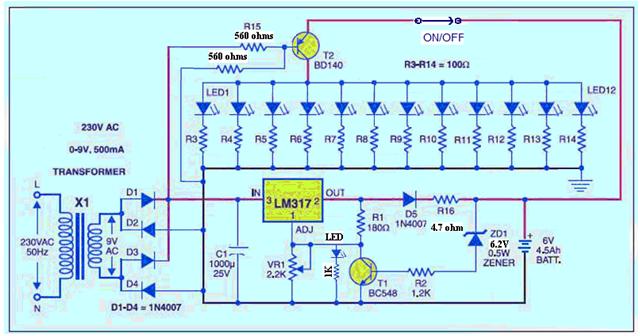
To understand the above circuit in a better way, it can be divided into two parts.
1. LED lamp circuit
2. The Battery charger circuit
2. The Battery charger circuit
LED Lamp circuit
1. All are white hi bright LEDs rated for 3Volt @ 25mA
2. The total current requirement is 12 X 25 = 300mA
3. This current has to flow through T2 – BD140 PNP transistor
4. The minimum current gain (hfe) of this transistor @ 500mA is 50
5. Hence the base current Ib requirement is Ic / hfe, 300 / 50 = 6mA
6. Base emitter drop of T2 at 500mA is 0.77 volt
7. With the fully charged battery at 6.9volt terminal voltage (for cycle operation use) the voltage available across the new bias resistance is (6.9 – 0.77)
8. Hence the bias resistance is = 6.13 / 6 = 1000ohms
9. As the battery drains the final terminal voltage will be 5.4volt
10. The bias resistance will be (5.4 – 0.77) / 6 = 770 ohms Hence a 680 ohms was preferred for bias resistance with drained battery also it will give enough brightness.
11. The very important information about BD140 is, as you view the pins, metal portion of the transistor facing down left is emitter centre collector and right is base. Most of the constructors make this mistake, relying on the convention that left base and right emitter. If you have made this mistake please correct it.
Once this portion is checked for reliable operation we will proceed to charger portion.
The Battery charger circuit
1. The battery requires a full terminal voltage of 6.9V at this point charger should cut off.
2. That is the voltage across the chain ZD1, R2 and T1 be should be 6.9 volt
3. T1 be voltage of 0.7 volt plus drop across R2 and zener voltage should be 6.9V
4. T1 be current = Ic / hfe
5. Ic is 1.25 / 180 = 7mA
6. Ibe = Ic / hfe of T1 i.e = 7 / 70 = 100uA
7. Drop across R2 =1.2 X .1 mA = 0.12volt
8. Hence Zener voltage = 6.9 – (0.7 + 0.12) = 6.08 the near by preferred zener voltage is 6.2 volt
9. Say the battery voltage at full charge will be 7 volt with 6.2 volt zener diode
10. To calculate R16 value for charging at 1 /10 th of the rated current of the battery 4.5AH / 10 = 450mAH
11. Transformer 9volt AC the voltage across C1 will be 9 X 1.414 = 12.6 volt
12. The drop across LM317 at 450mA current for good regulation is 3volt
13. The drop across protective diode D5 is 0.7 volt.
14. The voltage available at cathode of D5 is 12.6 – (3+0.7) = 8.9volt
15. The battery after fair discharge will be at 6 volt
16. Hence R16 = (8.9 – 7) / 0.45 = 6 ohms
17. The nearby standard value for operation is 5 ohms.
18. At the end point of battery 5.4 volt the maximum charging current can be of (8.9 – 5.4) / 5 = 0.7 amps well within the higher charging limit of the battery.
19. With this circuit over night the battery will get charged fully.
20. Over charging is taken care and protected by T1
Hope with the above guide line you can make your light work successfully.
More Modification!!!
Automatic LED Emergency Light with Under Voltage Cut Off Protection:
Dear Readers,
Tthis LED Emergency Light with an under voltage cut-off protection to protect battery from deep discharge. Once the battery terminal voltage falls below 5.7 volts the LEDs will be switched off. Take a look at the modified circuit shown below.

0 Comments:
Post a Comment